Paul Claret

Custom PCB Design for RF transimission and reception of morse code
Personal project of mine. The goal was to get started with a simple project of pcb design using KiCad and a project that also implied doing RF (which was something i had never seen in school)


(March 2025 - March 2025)
This is a simple project of mine. The goal was not to do something crazy with the pcb design and the RF module. This project goal was to start building pcb and learn how to design RF circuits...
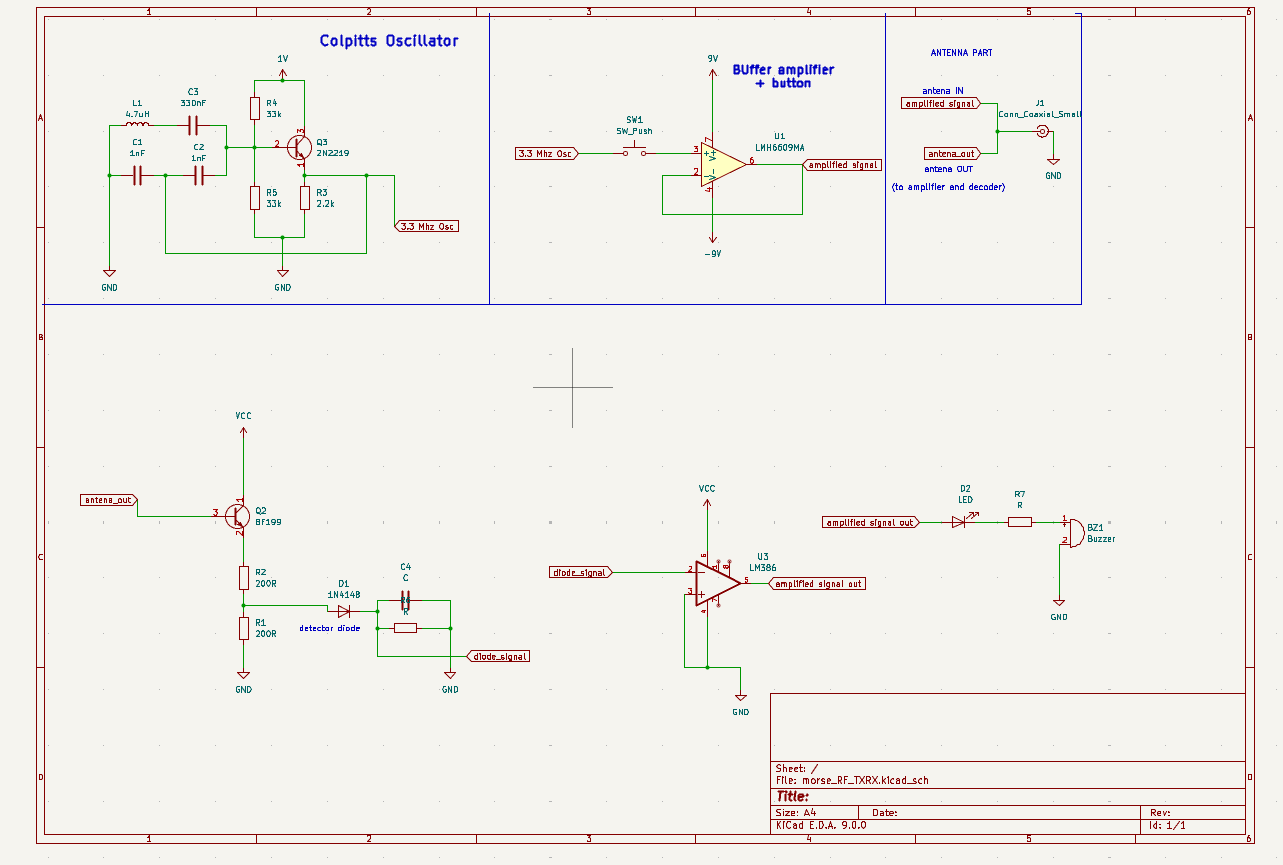
I had never been introduced to these courses after 3 years of my engineering school (2 years of prépas and 1 year of the engineering cycle). So i decided to learn on my own. I chose which frequency to use. In order to keep the pcb design and antenna small, I had the choice between multiple RF but i ended up choosing the 430–440 MHz frequency band because of the antenna size it implied. (That way, I didn't have to have an antenna of 30 meters XD). After this, I designed a Colpitts oscillator but realized, that it wouldn't be reliable at theses frequencies so I switched to a quartz. I also had to design amplifiers, filters and other modules on the board to get a signal that was interpretable. For the HMI, I just used a LED and buzzer since that part of the project wasn't what I wanted to learn or send time doing. My goal was really focused on the RF design part !
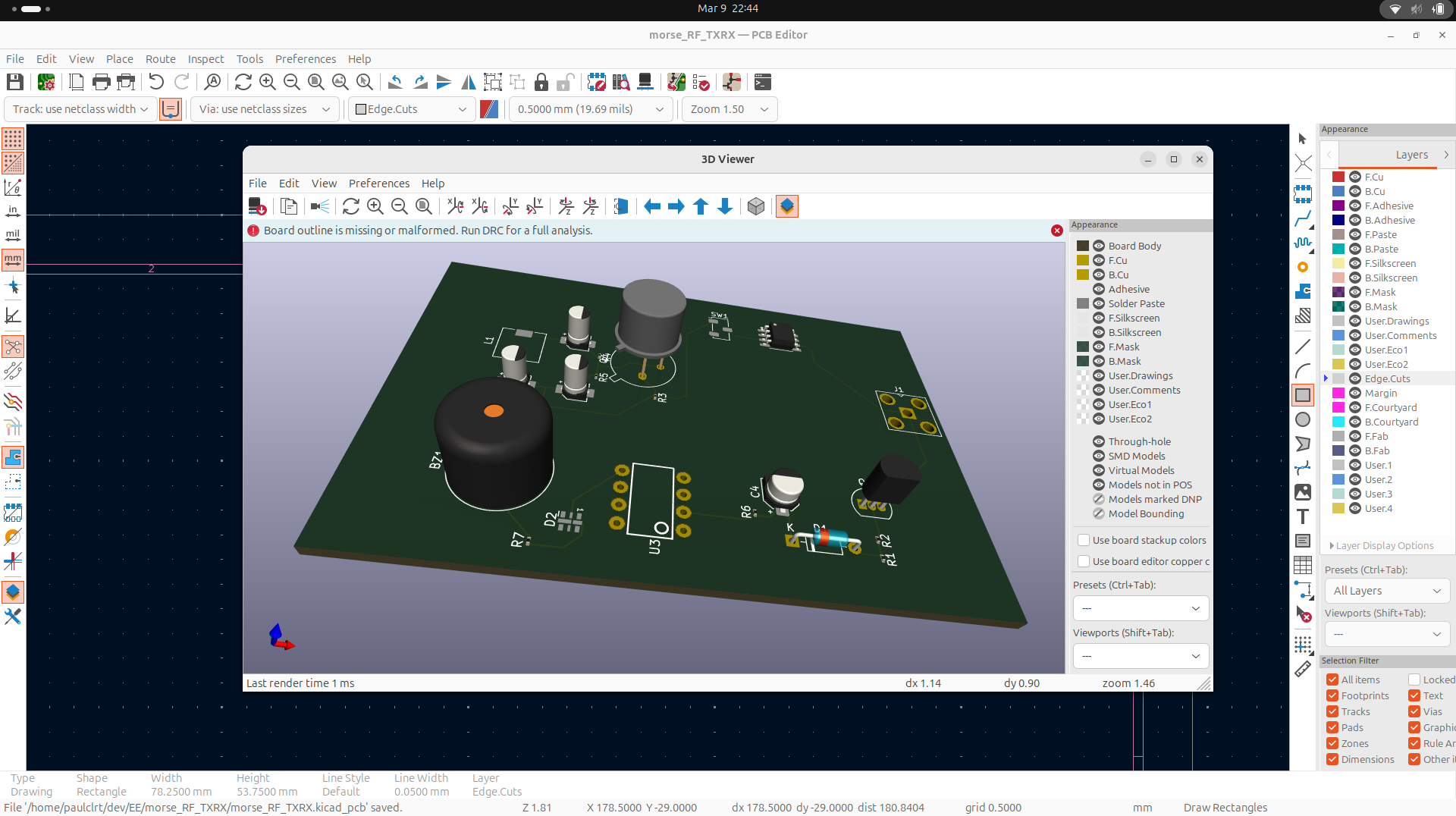
In the end, the board can send and receive signals from another board.
PS: the design is imperfect and I know it. That side project was simply a learning experience for me and not a professional one.
